
Fiber optic systems can offer CO2 plume insights in CCS applications, according to services firm Weatherford. (Source: Shutterstock.com)
Reducing the carbon footprint worldwide requires continuous, long-term reservoir monitoring information to ensure captured carbon remains in place in underground storage.
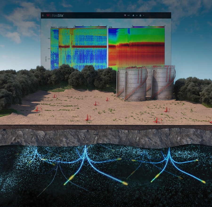
Robust and innovative fiber optic solutions are needed to support the development of storage-asset surveillance for carbon capture and storage (CCS) operations.
The Measurement Monitoring and Verification (MMV) program is an essential part in the CO2 storage life cycle, including early-stage site characterization, permit application, field development, injection monitoring compliance and post-injection storage monitoring. MMV deliverables are being embedded as part of the CCS operational process to demonstrate containment and conformance of CO2 being injected and sequestered in the reservoir permanently. With over 30 years of experience developing and installing fiber optic sensing systems, Weatherford recognizes the potential this technology has to meet some of the monitoring requirements specified in the MMV program.
Effective CO2 plume monitoring in injection wells is one of the key objectives in the MMV framework for upcoming CCS projects in the United States and around the world.
Distributed acoustic sensing (DAS) methodology, enabled through an optical cable as the sensor for both passive and active seismic monitoring, has opened new possibilities of design to incorporate fiber optic systems as a permanent seismic sensor in the architecture of the well.
The challenge for operators is overcoming the reluctance to transition from conventional methods of measurement to more innovative fiber optic measurement solutions that effectively meet the measurement-parameter thresholds.
Fiber optic deployment
There are several reasons fiber optic cable might need to be cemented behind casing, but fundamentally, it is done to enhance coupling to the formation, ensuring optimal measurement sensitivity. The fiber-optic cable should be installed, and preferably cemented, close to the sealing caprock position to promptly detect any microseismic activity or out-of-zone injection.
For thorough monitoring of plume saturation and migration, it’s essential to cement the fiber optic cable behind casing directly across the injection zone. Although embedding the fiber optic cable in cement during installation provides the most precise results and superior imaging quality, acceptable measurement outcomes can still be achieved if it’s deployed through tubing instead. When the reservoir section is intended to be cased and perforated, it becomes essential to mitigate the risk of potential cable damage during the perforation operation in this area.
In this scenario, Weatherford leverages the experience from system deployment in well environments for in-zone monitoring in oil and gas, and unconventional applications. Here, the fiber optic system is deployed in cemented annuli, and casing perforation is performed in the same vicinity as production through a method called oriented perforation.
During casing runs, optical cable is lowered to the desired depth using a specialized clamp system positioned over the area of interest, after which cementing is carried out. The clamp system is pre-installed to enable indication of the cable azimuth position inside the casing.
In the perforation stage, a wireline-deployed gun string is run in conjunction with an orientation tool to identify the clamp system behind the casing. This allows the predetermined charge direction string to be pointed away and perforated safely without risking damage to optical cables or gauges.

The additional data stream—gained through deploying a fixed sensor while still obtaining data from distributed measurement—is an added value for the operator.
The use of a single optical cable system allows for the installation of pressure and temperature sensors at the injection depth, enabling real-time monitoring of CO2 injection. This setup ensures that the injection rate and pressure remain within the frac gradient of the cap rock seal, a level of precision that was previously achievable only with tubing-conveyed options. Installing optical gauges in this environment is ideal because the transducer’s low mass enables it to withstand the high G loads typically experienced in the localized area of perforating gun discharge.
Technology deployment
Weatherford has performed the oriented perforation process in the U.S., Middle East and Asia. The deployment of this technology application worldwide has showcased the benefits of adopting a fiber optic system.
The optical system offers the advantage of improvements, enhancements or the addition of new sensing options post-installation. Operators have been able to go back to a 23-year-old optical-sensor system and still obtain data. By leveraging advancements in acoustic sensing processing and interpretation, Weatherford was able to extract additional insights by connecting a different surface instrument to the downhole optical pathway, a surface-instrument solution that was not available at the time of deployment over two decades ago.
Deploying a system that allows scope-of-improvement in data insights is crucial for CCS wells due to the longevity of the application and surveillance requirements in these reservoirs.
Skandar Gandi, is Weatherford's global segment lead for CCS and Steve Mathias is global adviser for reservoir monitoring.
Recommended Reading
Iraq to Seek Bids for Oil, Gas Contracts April 27
2024-04-18 - Iraq will auction 30 new oil and gas projects in two licensing rounds distributed across the country.

Halliburton’s Low-key M&A Strategy Remains Unchanged
2024-04-23 - Halliburton CEO Jeff Miller says expected organic growth generates more shareholder value than following consolidation trends, such as chief rival SLB’s plans to buy ChampionX.

E&P Highlights: April 22, 2024
2024-04-22 - Here’s a roundup of the latest E&P headlines, including a standardization MoU and new contract awards.

Deepwater Roundup 2024: Americas
2024-04-23 - The final part of Hart Energy E&P’s Deepwater Roundup focuses on projects coming online in the Americas from 2023 until the end of the decade.

Northern Midland: EOG Brings on Dean Oil Well in SE Dawson Stepout
2024-06-18 - EOG Resources has not stated yet that Dawson County is the location of its new “stealth play.” It remained mum in an investment-banking conference this week.